


X-Ray and CT Inspection of Die Castings: Methods, Standards and Limits
A die casting can look perfect and still contain pores in a sealing face or a load-bearing rib. X-ray methods make the inside visible without destroying the part. Whether a 2D image in the production cycle or a CT scan in the lab fits depends on the question, the part and the agreed acceptance criteria.
How Are Die Castings Inspected with X-Rays?
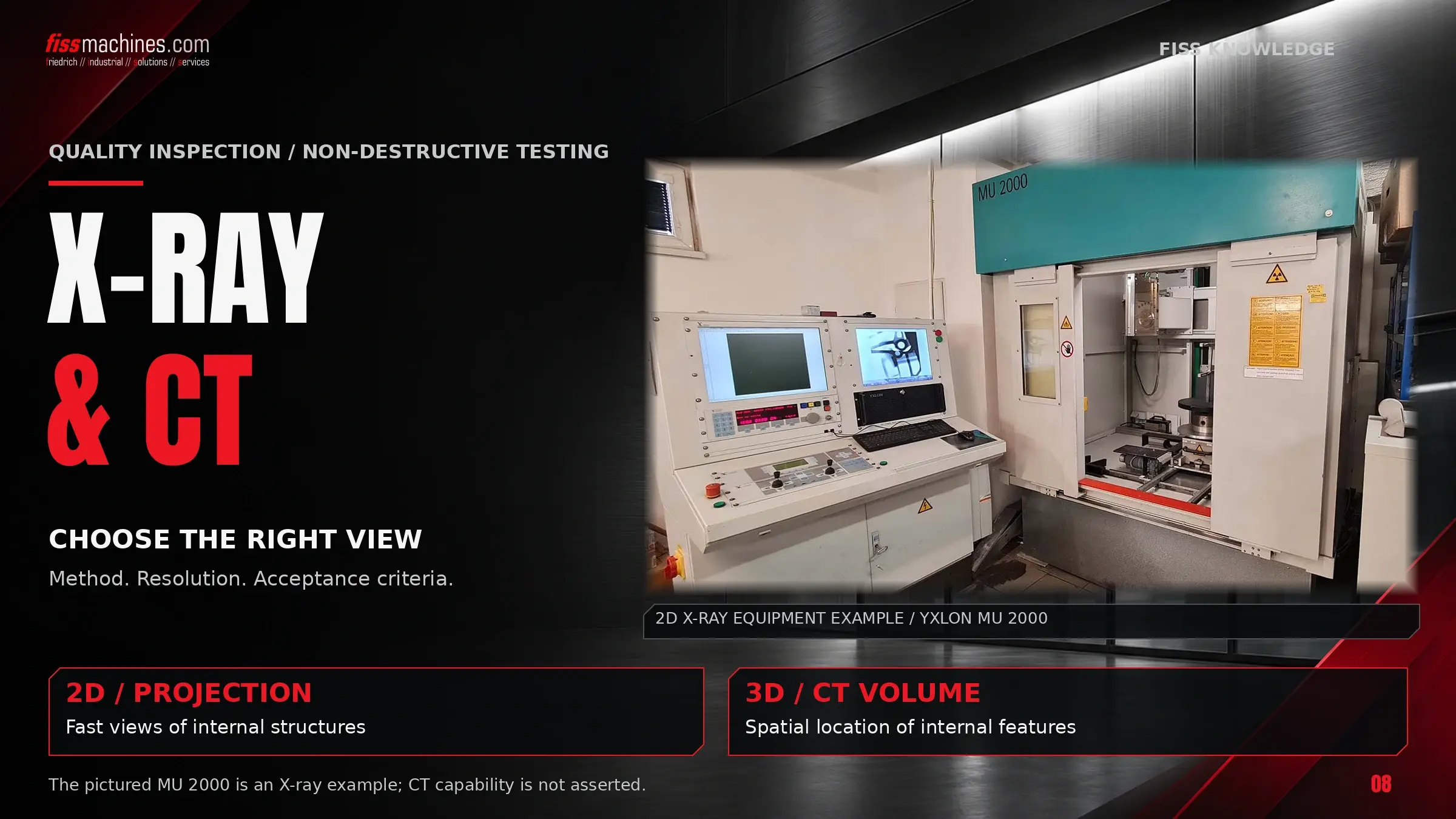
X-ray inspection of die castings uses the different absorption of X-rays by sound metal and by voids: pores, shrinkage and inclusions appear as contrast differences. In production, radioscopy with digital detectors delivers real-time 2D images, often with automated defect recognition. Industrial computed tomography (CT) shows position, size and volume of each defect in 3D, but takes much longer per part.
Standards such as ASTM E505 or the BDG guidelines provide a common language for defect types and severity levels. What is acceptable for a specific part is agreed between customer and foundry.
Three Methods, Three Typical Uses
Radiation passes through the part, and a detector or film records how much arrives – where metal is missing, more gets through. The methods differ in how the image is captured and whether the result is a projection or a volume.
Radioscopy
Live image on a digital detector, part moved by a manipulator. Fast enough for 100% inspection in the cycle.
Film and Digital Radiography
Single exposures on film, imaging plates (CR) or detector arrays (DDA), mainly for sampling and documentation.
Computed Tomography
Many projections reconstructed into a volume: exact defect location and size, plus geometry.
X-ray and CT find internal defects but do not explain them; root causes are covered in Die Casting Defects Explained.
Radioscopy and Radiography: The 2D View
In radioscopy, the casting is moved between X-ray tube and flat-panel detector, and inspector or software evaluate live images from defined viewing angles. For one of its systems for large structural castings, ZEISS states about 3 to 3.5 seconds per view (manufacturer statement); the time per part depends on the number of views.
Radiography records single images – on film, increasingly on imaging plates or digital detector arrays. For castings, EN 12681-1 covers film and EN 12681-2 digital detectors, aiming at a sensitivity equivalent to film.
Industrial CT: Voxel Size, Part Size and Scan Time
In CT, the part rotates while the detector records many projections, which are reconstructed into a volume of voxels. If the whole part must fit into the field of view, the voxel size is roughly the scanned width divided by the number of detector pixels across. Large parts mean coarser voxels – unless only a region of interest is scanned at higher magnification.
| Scanned width | Approx. voxel size* | Typical use |
|---|---|---|
| 30 mm (sample, cut-out) | ≈ 0.01 mm | Detailed pore analysis, cut-outs from larger parts |
| 150 mm (housing, bracket) | ≈ 0.05 mm | Porosity analysis and nominal/actual comparison of complete parts |
| 400 mm (large housing) | ≈ 0.13 mm | Larger defects, overview scans, first-article inspection |
*Illustrative estimate for a detector about 3,000 pixels wide; real values depend on system, scan mode and material. A pore must cover several voxels to be measured reliably, so define the smallest relevant pore size before scanning.
- Porosity analysis: volume, size, shape and position of each pore per part region
- Nominal/actual comparison: scan versus CAD model, including inner contours
- Wall thickness analysis: thin areas and core shift in housings and channels
- Limitations: scan and evaluation from minutes to hours, artefacts on large parts, high cost
Inline Inspection or Sampling?
The choice depends on part risk and cell cycle time. Many plants combine fast 2D inspection in the line with CT in the lab for process qualification and root-cause analysis.
| Criterion | Inline / at-line radioscopy | Offline sampling (2D or CT) |
|---|---|---|
| Coverage | Up to 100% of parts, defined zones | Selected parts per shift, batch or die change |
| Evaluation | Automated defect recognition (ADR) or operator | Inspector, CT evaluation software |
| Information | Pass/fail per view, defect indication | Exact defect geometry, trends, root cause |
| Main limitation | Must keep pace with the cell cycle | Defects between samples go unnoticed |
Automated defect recognition evaluates images against learned or rule-based criteria. It must be taught with real good and bad parts and checked regularly for false calls and slip-through. Linking each result to the shot number allows comparison with shot curves; how sorting and marking fit into the cell is covered in Automation in the Die Casting Cell.
Which Standards Are Relevant?
These documents are frequently referenced for die castings. Check the current edition before writing one into a drawing or supply agreement.
| Document | Content | Note |
|---|---|---|
| ASTM E505 | Reference radiographs for aluminium and magnesium die castings: discontinuity categories in four severity levels | Current edition E505-22; film only, for digital images ASTM E2973 |
| ASTM E2973 | Digital reference images for aluminium and magnesium die castings | Current edition E2973-22 |
| EN 12681-1 / -2 | Founding – radiographic testing: film techniques (Part 1) and digital detectors (Part 2) | Editions 2017; a revision of Part 1 is in preparation |
| VDG P 201, BDG P 202 | Volume deficits (porosity) of non-ferrous castings, evaluated in sections | German guidelines, 2D evaluation |
| BDG P 203 | Porosity analysis of Al, Mg and Zn castings with industrial CT | Extends P 201/P 202 to 3D, evaluation by part region |
| ISO 15708 series | Radiation methods for computed tomography: terminology, principles, operation, qualification | Several parts revised since 2024 |
ISO 10893 covers steel tubes and is not relevant for die castings.
Acceptance Criteria Are a Matter of Agreement
Reference radiographs show what a severity level looks like, not which level a part may have; ASTM E505 assumes an agreement between purchaser and manufacturer. A typical approach:
Define zones
Mark sealing faces, threads, load-bearing sections and machined surfaces on the drawing.
Set limits per zone
Severity level or, for CT, maximum pore size, volume or distance to machined surfaces.
Fix method and scope
Agree on method, views or CT resolution, frequency and reference standard.
Qualify with real parts
Prove with parts from the production die that the method finds the relevant defects.
If porosity sits near machined surfaces, the fix lies in the process: see Mold Filling and Vacuum in Die Casting and Aluminium Melt Quality.
Where X-Ray and CT Reach Their Limits
- Wall thickness and contrast: the thicker the section, the weaker the contrast of a given void.
- Orientation: thin, flat cracks and cold shuts show mainly when the beam runs along their plane.
- Resolution: micro-porosity below detector or voxel resolution is missed, even if it affects leak tightness.
- Surface defects: flow marks and surface laps are better found visually.
- Cost and time: CT for every part is rarely economical.
Choose the Method to Fit the Question
Radioscopy with automated evaluation inspects many parts inline, radiography documents samples, and CT answers the detailed questions about pore position, size and geometry. All three need agreed acceptance criteria per zone, a qualified procedure – and a casting process that keeps porosity low in the first place.
Questions About X-Ray and CT Inspection of Die Castings
What Is the Difference Between Radiography and Radioscopy?
Radiography records single images; radioscopy produces live images while the part moves, suited to fast production inspection.
Does ASTM E505 Define Which Porosity Is Acceptable?
No. It shows categories and severity levels; the acceptable level is agreed between purchaser and manufacturer.
Can CT Replace a Leak Test?
Generally not. Leakage paths can be smaller than CT resolution; the leak test remains the functional proof.
How Small Can a Pore Be to Still Be Detected by CT?
It depends on voxel size and thus on the scanned size. A pore must cover several voxels; small parts or cut-outs allow much finer resolution.
Die Casting Machines from FISS.
Stable casting quality starts with the machine. FISS supplies used cold-chamber die casting machines and helps you choose the right equipment.
Sources
ASTM International: E505-22 Standard Reference Radiographs for Inspection of Aluminum and Magnesium Die Castings and E2973-22 Digital Reference Images for Inspection of Aluminum and Magnesium Die Castings, abstracts via store.astm.org and dinmedia.de, accessed 5 November 2026.
CEN: EN 12681-1:2017 Founding – Radiographic testing – Part 1: Film techniques and EN 12681-2:2017 Part 2: Techniques with digital detectors, scope summaries via standards catalogues, accessed 5 November 2026.
ISO: ISO 15708 Non-destructive testing – Radiation methods for computed tomography, Parts 1–4, catalogue entries iso.org, accessed 5 November 2026.
VDG/BDG: P 201, P 202 Volume deficits of castings made from aluminium, magnesium and zinc casting alloys (2010) and P 203 (CT porosity analysis, 2019), as described by DIN Media, Volume Graphics and QZ Qualität und Zuverlässigkeit 07/2021, accessed 5 November 2026.
ZEISS: 2D X-ray inspection systems and press release ZEISS OMNIA GC 220-180, 2025, zeiss.com, accessed 5 November 2026 (manufacturer statements).
DGUV: FAQ Röntgenanlage, stationäre (notification and licensing under the Radiation Protection Act), dguv.de, accessed 5 November 2026.
